Product Description
Product Description
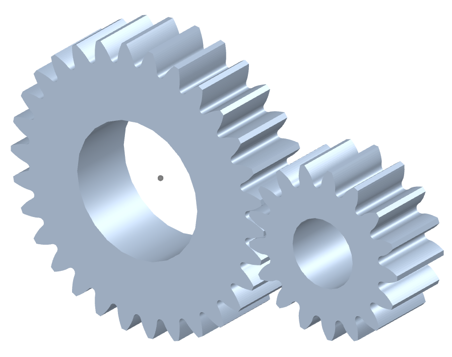
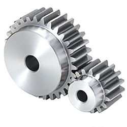
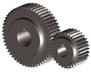
Transmission Custom Precision cylindrical bronze sun ring Toothed Spiral Helical Spur Gear
| Item | Customized machined machining gears | |
| Process | CNC machining,CNC milling, cnc lathe machining | |
| material | steel, stainless steel, carbon steel,brass,C360 brass copper, aluminum 7075,7068 brass,C360 brass copper, aluminum Nylon, PA66, NYLON , ABS, PP,PC,PE,POM,PVC,PU,TPR,TPE,TPU,PA,PET,HDPE,PMMA etc | |
| Quality Control | ISO9001 and ISO14001 | |
| Dimension bore tolerances | -/+0.01mm | |
| Quality standard | AGMA, JIS, DIN | |
| Surface treatment | Blackening, plated, anodizing, hard anodizing etc | |
| Gear hardness | 30 to 60 H.R.C | |
| Size/Color | Gears and parts dimensions are according to drawings from customer, and colors are customized | |
| Surface treatment | Polished or matte surface, painting, texture, vacuum aluminizing and can be stamped with logo etc. | |
| Dimensions Tolerance | ±0.01mm or more precise | |
| Samples confirmation and approval | samples shipped for confirmation and shipping cost paid by customers | |
| Package | Inner clear plastic bag/outside carton/wooden pallets/ or any other special package as per customer’s requirements. | |
| Delivery Time | Total takes 2~~8weeks usually | |
| Shipping |
Usual FEDEX, UPS, DHL, TNT, EMS or base on customer’s requirement. |
Production management:
1. The workers are trained to inspect the gears and notice any defect in production in time.
2. QC will check 1pcs every 100pcs in CNC machining, and gears will meet all dimension tolerances.
3. Gears will be inspected at every step, and gears will be inspected before shipment, and all inspection records will be kept in our factory for 3 years.
4. Our sales will send you pictures at every gears production steps, and you will know the detailed production status, and you can notice any possibility of mistake, for our sales, QC and workers are keeping close watch on all production.
5. You will feel us working very carefully to assure the quality and easy to work with,
6. we cherish every inquiry, every opportunity to make gears and parts and cherish every customer.
QUALITY CONTROL PROCESS:
1) Inspecting the raw material –IQC)
2) Checking the details before the production line operated
3) Have full inspection and routing inspection during mass production—In process quality control (IPQC)
4) Checking the gears after production finished—- (FQC)
5) Checking the gears after they are finished—–Outgoing quality control (OQC)
Service:
1. Molds designs as per customers’ gears drawing;
2. Submitting molds drawings to customers to review and confirm before mols production.
3. Providing samples with whole dimensions and cosmetic inspection report, material certification to customers.
4. Providing inspection report of important dimensions and cosmetic in batches parts.
Packing and shipment:
1. Gears are well and carefully packed in PP bags in CTNS, strong enough for express shipping, air shipment or sea shipment.
2. Air shipment, sea shipment or shipment by DHL, UPS, FedEx or TNT are availabe.
3. Trade terms: EXW, FOB HangZhou, or CIF
4. All shippings will be carefully arranged and will reach your places fast and safely.
FAQ
Q1: How to guarantee the Quality of gears and parts?
We are ISO 9001:2008 certified factory and we have the integrated system for industrial parts quality control. We have IQC (incoming quality control),
IPQCS (in process quality control section), FQC (final quality control) and OQC (out-going quality control) to control each process of industrial parts prodution.
Q2: What are the Advantage of your gears and parts?
Our advantage is the competitive and reasonable prices, fast delivery and high quality. Our eployees are responsible-oriented, friendly-oriented,and dilient-oriented.
Our industrial parts products are featured by strict tolerance, smooth finish and long-life performance.
Q3: what are our machining equipments?
Our machining equipments include plasticn injection machinies, CNC milling machines, CNC turning machines, stamping machines, hobbing machines, automatic lathe machines, tapping machines, grinding machines, cutting machines and so on.
Q4: What shipping ways do you use?
Generally, we will use UPS DHL or FEDEX and sea shipping
5: What materials can you process?
For plastic injection gears and parts, the materials are Nylon, PA66, NYLON with 30% glass fibre, ABS, PP,PC,PE,POM,PVC,PU,TPR,TPE,TPU,PA,PET,HDPE,PMMA etc.
For metal and machining gears and parts, the materials are brass, bronze, copper, stainless steel, steel, aluminum, titanium plastic etc.
Q6: How long is the Delivery for Your gears and parts?
Generally , it will take us 15 working days for injection or machining, and we will try to shorten our lead time.
/* March 10, 2571 17:59:20 */!function(){function s(e,r){var a,o={};try{e&&e.split(“,”).forEach(function(e,t){e&&(a=e.match(/(.*?):(.*)$/))&&1
| Application: | Motor, Electric Cars, Machinery, Toy, Agricultural Machinery, Car |
|---|---|
| Hardness: | Hardened Tooth Surface |
| Gear Position: | External Gear |
| Manufacturing Method: | Cut Gear |
| Toothed Portion Shape: | Curved Gear |
| Material: | Stainless Steel |
| Samples: |
US$ 10/Piece
1 Piece(Min.Order) | |
|---|
| Customization: |
Available
| Customized Request |
|---|
How do you ensure proper alignment when connecting spur gears?
Proper alignment is crucial when connecting spur gears to ensure smooth and efficient gear operation. Here’s a detailed explanation of how to ensure proper alignment when connecting spur gears:
- Visual Inspection: Start by visually inspecting the gears, gear shafts, and associated components for any visible misalignment or damage. Look for signs of wear, uneven tooth engagement, or any abnormalities that may affect alignment.
- Shaft Alignment: Align the gear shafts accurately before connecting the gears. Proper shaft alignment ensures that the gears are positioned correctly relative to each other. This can be achieved through various alignment techniques, such as using alignment tools, laser alignment systems, or measuring devices. The goal is to ensure parallel or coaxial alignment between the gear shafts.
- Backlash Adjustment: Adjust the backlash between the gear teeth to achieve proper alignment. Backlash refers to the slight gap between the mating teeth of gears. It is important to maintain an appropriate amount of backlash to allow for smooth gear engagement and minimize the risk of binding or jamming. Follow the manufacturer’s recommendations or industry standards for the recommended backlash range and adjust as necessary during gear installation.
- Check Gear Mesh: Verify the gear meshing pattern to ensure proper alignment. The gear teeth should mesh smoothly and evenly without any signs of excessive or uneven contact. If there are indications of improper meshing, such as concentrated contact on a specific area of the tooth, it may imply misalignment or other issues that need to be addressed.
- Shim Adjustment: If misalignment is detected, shimming can be employed to correct it. Shimming involves placing thin metal shims between the gear and the shaft to adjust the positioning and alignment. Shims are available in various thicknesses, allowing for precise alignment adjustments. Careful measurement and selection of the appropriate shim thickness can help achieve the desired alignment.
- Tightening Bolts: When connecting the gears to the shafts, ensure that the bolts or fasteners are tightened evenly and to the recommended torque specifications. Uneven tightening can introduce misalignment or uneven load distribution, leading to gear misalignment and potential issues.
- Post-Installation Verification: After connecting the gears, perform a final verification of the alignment. Rotate the gears manually or through the gear system’s intended operation and observe the gear meshing behavior. Look for any signs of abnormal noise, vibration, or irregular tooth engagement. If any issues are detected, further adjustments or inspections may be necessary.
- Regular Maintenance: Implement a proactive maintenance program that includes periodic inspections and alignment verification. Gears can experience wear or misalignment over time due to factors such as load variations, temperature changes, or prolonged operation. Regular maintenance allows for early detection and correction of alignment issues, ensuring optimal gear performance and longevity.
Proper alignment is essential for maximizing the efficiency, durability, and reliability of spur gear systems. By following these alignment practices and considering the manufacturer’s recommendations, industry standards, and expert advice, you can ensure proper alignment when connecting spur gears.
It’s important to note that the specific alignment techniques and procedures may vary depending on the gear system’s design, size, application, and other factors. Consulting with gear manufacturers, engineers, or alignment specialists can provide further guidance on the recommended alignment practices for your specific gear system.
What are the advantages and disadvantages of using spur gears?
Spur gears offer several advantages and disadvantages when used in mechanical systems. Here’s a detailed explanation of the advantages and disadvantages of using spur gears:
Advantages of Spur Gears:
- Simplicity: Spur gears have a simple and straightforward design, consisting of cylindrical gears with straight teeth. Their simplicity facilitates ease of manufacturing, installation, and maintenance.
- Efficiency: Spur gears are highly efficient in transmitting power from one shaft to another. They have minimal sliding friction between the gear teeth, resulting in high mechanical efficiency.
- Cost-Effectiveness: Due to their simple design and ease of production, spur gears are generally more cost-effective compared to other types of gears. They are widely available and can be manufactured in large quantities at a reasonable cost.
- Compactness: Spur gears have a compact design, making them suitable for applications where space is limited. They can be arranged in parallel or stacked configurations to achieve the desired gear ratios within a confined space.
- High Load Capacity: Spur gears can handle high load capacities and transmit substantial amounts of torque. Their teeth are designed to distribute the load evenly across the gear face, resulting in improved load-bearing capabilities.
- Precision: Spur gears provide precise and predictable motion due to the simplicity of their tooth engagement. This makes them suitable for applications that require accurate positioning and synchronization.
Disadvantages of Spur Gears:
- Noisy Operation: Spur gears can produce noise during operation, especially at high speeds. The engagement of the gear teeth generates impact and vibration, resulting in noise that may require additional measures to mitigate.
- Axial Thrust: Spur gears generate axial thrust forces along the gear shafts due to the parallel arrangement of their teeth. This thrust must be properly managed using thrust bearings or other means to prevent excessive axial loading on the gear shafts.
- Limited Speed Ratio: Spur gears are primarily designed for applications with moderate speed ratios. They are less suitable for high-speed applications due to the limitations imposed by the tooth engagement and potential for increased noise and vibration.
- Unidirectional Operation: Spur gears are typically designed for unidirectional power transmission. Reversing the direction of rotation can cause noise, impact, and increased wear due to the abrupt change in tooth engagement.
- Prone to Wear: The sliding contact between the gear teeth in spur gears can result in wear over time, especially under heavy loads or inadequate lubrication. Regular maintenance and proper lubrication are necessary to minimize wear and extend gear life.
It’s important to consider these advantages and disadvantages when selecting gear types for specific applications. While spur gears are well-suited for many applications, other gear types, such as helical gears or bevel gears, may be more suitable in certain situations depending on the requirements and operating conditions.
What is a spur gear and how does it work?
A spur gear is a type of cylindrical gear with straight teeth that are parallel to the gear axis. It is one of the most common and simplest types of gears used in various mechanical systems. Spur gears work by meshing together to transmit rotational motion and torque between two parallel shafts. Here’s a detailed explanation of spur gears and how they work:
A spur gear consists of two or more gears with cylindrical shapes and an equal number of teeth. These gears are mounted on parallel shafts, and their teeth mesh together to transfer rotational motion from one gear to another. The gear with power input is called the “drive gear” or “driver,” while the gear receiving the power output is called the “driven gear” or “follower.”
The key characteristics and components of spur gears include:
- Teeth: Spur gears have straight teeth that are cut parallel to the shaft axis. The teeth are evenly spaced around the circumference of the gear. The number of teeth determines the gear ratio and affects the speed and torque transmission between the gears.
- Pitch Diameter: The pitch diameter is the theoretical diameter of the gear at the point where the teeth mesh. It is determined by the number of teeth and the module or diametral pitch of the gear.
- Module or Diametral Pitch: The module is a parameter used in metric gear systems, while the diametral pitch is used in imperial gear systems. They define the tooth size and spacing of the gear. The module is the ratio of the pitch diameter to the number of teeth, while the diametral pitch is the number of teeth per inch of pitch diameter.
- Pressure Angle: The pressure angle is the angle between the line tangent to the tooth profile at the pitch point and a line perpendicular to the gear axis. Common pressure angles for spur gears are 20 degrees and 14.5 degrees.
- Meshing: Spur gears mesh by engaging their teeth, creating a point or line contact between the contacting surfaces. The teeth transfer rotational motion and torque from the drive gear to the driven gear.
- Gear Ratio: The gear ratio is determined by the number of teeth on the drive gear and the driven gear. It defines the relationship between the input speed and the output speed. The gear ratio can be calculated by dividing the number of teeth on the driven gear by the number of teeth on the drive gear.
- Operation: As the drive gear rotates, its teeth come into contact with the teeth of the driven gear. The contact between the teeth transfers rotational motion and torque from the drive gear to the driven gear. The meshing teeth maintain a constant speed ratio, allowing for the transmission of power between the shafts. The direction of rotation can be changed by meshing gears with an odd or even number of teeth.
Spur gears offer several advantages, including simplicity, ease of manufacture, efficiency, and reliability. They are commonly used in a wide range of applications, including machinery, automotive systems, appliances, power tools, and more.
In conclusion, spur gears are cylindrical gears with straight teeth that mesh together to transfer rotational motion and torque between parallel shafts. Their simple and efficient design makes them a popular choice for various mechanical systems.


editor by CX 2024-01-08